The melting section of a float glass furnace is where the batch material is melted, and the molten glass is clarified and homogenized. The melting section consists of a melting zone and a clarifying zone; vertically, it is divided into an upper flame space and a lower furnace pool. The upper space, also called the flame space, is a flame-filled space enclosed by the front wall, the surface of the molten glass, the large arch of the furnace roof, and the breast wall of the furnace. The lower furnace pool consists of the pool bottom and pool walls. In other words, the function of the melting zone is to form molten glass from the batch material through physical and chemical reactions at high temperatures, while the function of the clarifying zone is to quickly and completely remove air bubbles from the formed molten glass to achieve the required glass quality for production.
The flame space is filled with hot flame gases supplied by a heat source. These flame gases use their own heat to melt the batch material and also radiate heat to the molten glass, furnace walls, and furnace roof. The flame space should be able to ensure complete combustion of the fuel, guaranteeing the heat required for glass melting, clarification, and homogenization, while minimizing heat loss.
Tank Furnace
The tank furnace is where the batch of raw materials is melted into molten glass and then clarified and homogenized. It should be able to supply a sufficient quantity of fully melted, transparent molten glass. To ensure the furnace tank reaches a certain service life, the tank wall thickness is generally 250–300 mm, while the tank bottom thickness varies depending on the insulation. Without insulation, the tank bottom thickness is generally 300 mm.
(1) Front Wall Structure
The front wall is the front end wall of the flame space in the melting section, spanning the upper part of the feeding pool to block the escape of hot gases (including flames) and heat radiation from the feeding port at the front of the melting furnace. Because the front wall is easily damaged by flame burns and material powder erosion, and is prone to deformation during hot air kiln baking, most float glass manufacturers in China currently use L-shaped hanging walls.
Compared to the previous multi-arched design, the L-shaped hanging wall has advantages such as extending the service life of the front wall, enhancing energy efficiency, improving the on-site environment, protecting the feeding machine, increasing melting speed, reducing dust emissions, and increasing the lifespan of the grid. During the design of the front wall, attention should be paid to reasonably selecting the distance from the center line of the small furnace in the melting section. Too small a distance will accelerate the burn-off of the front wall, reduce the preheating effect of the batch material, and increase the burn-off and blockage of the small furnace; too large a distance will result in excessively low temperatures in the feeding pool, melting of the material pile, and difficulty in advancing the material. Currently, the distance between the front wall and the centerline of the melting furnace in domestic float glass production lines generally ranges from 3.2 to 4.3 meters, depending on the fuel and tonnage.
① Arched Front Wall Structure
This type of front wall consists of two or three layers of arches and refractory bricks laid on top of the arches. A fire baffle is added at the arched opening below the front wall to prevent flame ejection, thus conserving fuel and protecting the feeding machine. The fire baffle’s load-bearing capacity is provided by a large water tank spanning the feeding pool. Knife-handle-shaped refractory bricks are hung on the water tank to prevent direct flame contact with the water tank. Strip bricks are stacked on top of the knife-handle shaped bricks. Due to safety factors, the span of this type of front wall is limited by its span-to-width ratio, generally not exceeding 7 meters. Even so, the front arch and fire baffle are easily damaged by flame burns and alkaline atmosphere corrosion. Damaged fire baffles and water tanks can be repaired and replaced by heat treatment. Once the front arch is severely damaged by fire, it can only be repaired by cold water drainage. Therefore, this type of front wall structure is being phased out in float glass melting furnaces, although it is still used in flat glass melting furnaces other than float glass furnaces.
The conventional arched front wall structure is limited by span and safety factors. To further increase the melting area, it is necessary to widen the feeding pool and expand the feeding surface. To resolve this contradiction, the L-shaped hanging wall was developed.
②L-shaped Hanging Wall Structure
Large float glass melting furnaces widely use the L-shaped front hanging wall. This hanging wall is independently suspended, and its height above the molten glass surface can be adjusted using mechanical jacks. The L-shaped hanging wall is constructed of heat-resistant steel and refractory materials. Its structural safety is not affected by its width. The width of the L-shaped hanging wall can be the same as the melting pool, thus meeting the design requirements of equal or near-equal width feeding pools. Using an L-shaped hanging wall while lengthening the feeding pool not only reduces dust but also enhances the pre-melting effect on the batch materials. The L-shaped suspended wall is divided into a straight section and an L-shaped section. The straight section uses high-quality silica bricks as refractory material, while the nose section uses sintered mullite and sintered zircon. The outer wall of the suspended wall is insulated with ceramic fiber felt, and a water jacket is installed at the front end of the nose section to seal it after cooling.
(2) Breast Wall Structure
Due to varying degrees of erosion and repair times in different parts of a float glass melting furnace, the breast wall, main arch, and furnace pool are divided into three separate support sections to separate the most severely damaged parts. The load is ultimately transferred to the steel structure at the furnace bottom. The load on the breast wall is transferred from the breast wall support plate (made of cast iron or angle steel) and the lower support iron to the columns, and finally to the steel structure at the furnace bottom.
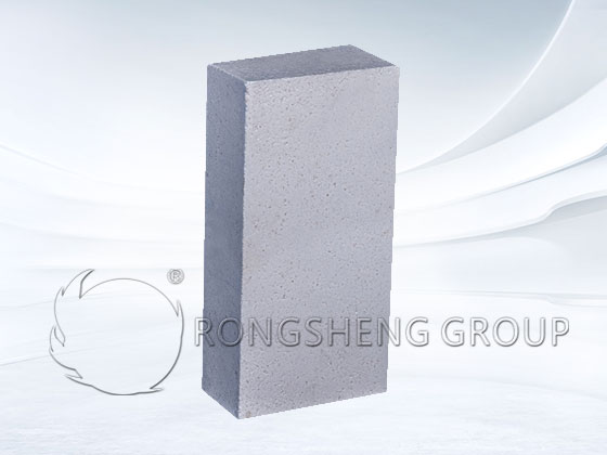
The breast wall design must ensure sufficient strength at high temperatures. Hook bricks are a key component; they are installed at the bottom of the breast wall to block the flames inside the furnace, preventing them from penetrating and damaging the breast wall support plate and the lower support iron. Generally, AZS33 electrofused bricks are used for the breast wall in the melting zone, low-creep, crack-resistant sintered zircon bricks are used for the upper gap bricks, and high-quality silica bricks are generally used for the breast wall in the refining zone.
The height of the breast wall depends on factors such as the type and quality of fuel, melting rate, melting heat consumption, furnace size, heat dissipation, and gas layer thickness.
Theoretically, as long as the refractory material used for the breast wall is resistant to erosion, the breast wall will not be a critical component affecting the lifespan of the melting furnace. However, in actual use, many melting furnaces experience shortened lifespans due to the inward tilting of the breast wall in the melting zone. Some furnaces even experience breast wall collapse in later stages due to untimely material discharge. The main reason for this is that the breast wall support plate tilts (outer side higher than inner side) when the tie rods are tightened after the main arch is constructed, causing the breast wall to tilt inward. Another reason is that after the pool wall bricks are tied, the breast wall support plate is exposed to the flame space, causing deformation of the support plate and resulting in inward tilting of the breast wall. To reduce or avoid this phenomenon, the design of the melting furnace breast wall has been improved. The characteristics of this structure are the elimination of the gap bricks, the main arch arch foot directly abutting the breast wall, the lowering of the breast wall support plate, the intentional inward tilting of the upper breast wall, the use of three layers of zircon bricks for the main arch side arch bricks, and the elimination of the hook design for the hook bricks in the melting zone. This avoids the inward tilting of the breast wall caused by the breakage of the hook bricks due to the quality of the electrofused AZS hook bricks. In addition, some large melting furnaces have replaced the 50mm thick ordinary carbon steel pallets with 60mm thick medium-silicon ductile iron pallets, which has also yielded good results.
(3) Arch Structure
The function of the arch is to form a flame space with the breast wall and front wall, and at the same time, it can also serve as a medium for heat radiation from the flame to the material and molten glass. That is, it absorbs the heat released during fuel combustion and then radiates it to the surface of the molten glass.
The weight of the arch is transferred from the steel arch slag through the upper iron plate and the columns to the steel structure at the bottom of the furnace.
The height and characteristics of the arch can be reflected by the span ratio. From a thermal perspective, a lower arch is beneficial, as it can radiate heat to the molten glass as much as possible. Reducing the height of the arch can be achieved by reducing the height of the breast wall and reducing the number of arch spans. However, the height of the breast wall is constrained by factors such as the small furnace nozzle and the structural strength of the arch; the smaller the span height, the greater the thrust, but the less heat dissipation. Reducing the number of arch sections increases the horizontal thrust of the main arch, increasing its instability. The span ratio of the main arch section in a large float glass melting furnace is generally around 1:8. Depending on the length of the melting section, the main arch can be divided into several sections, generally at least three. During construction, an expansion joint of approximately 100-120 mm is left between each arch section, with wider expansion joints at the top of the arch at the front and rear gable walls.
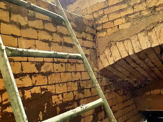
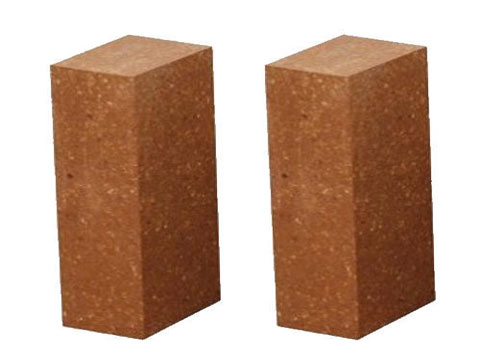
The main arch is generally constructed with high-quality silica bricks in a wedge shape. The horizontal joints are laid in a staggered pattern. The size of the mortar joints (also known as mud joints) is determined by the specific requirements of the mortar used, generally 1-2 mm.
The main arch slag in float glass melting furnaces is mostly made of steel slag and requires air cooling. The extended lines of the inclined surfaces of the two steel arch slags must pass through the center of the main arch arc, and the included angle formed is the central angle of the main arch.
The lifespan of the main arch determines the overall lifespan of the furnace. The weak points of the main arch during use include holes such as temperature and pressure measuring holes, the transverse joints of the main arch bricks (also known as the top joints), the arch heads of each section, and the edge arch sections. During normal furnace operation, the furnace is under positive pressure, and the various holes on the arch top are easily enlarged by flame penetration. If the edge arches are not in close contact with the steel arch slag, they are easily eroded and burned by the flames. Therefore, these areas should use high-performance refractory materials; currently, sintered zircon bricks are commonly used.
(4) Structure of the Pool Wall and Bottom
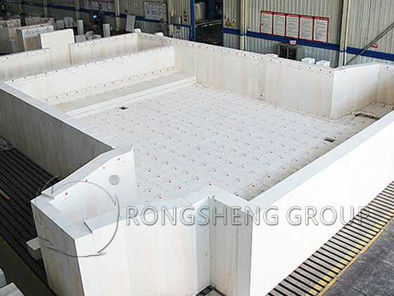
The furnace pool consists of two parts: the pool wall and the pool bottom, both constructed of large bricks. The furnace pool is built on a steel structure beam supported by the furnace columns below the furnace. The entire weight of the furnace pool and the weight of the molten glass it contains are borne by the steel structure supported by the furnace columns below the furnace. The furnace columns of float glass melting furnaces are generally made of concrete or steel. I-beams or H-beams are erected on top of the furnace columns along the length of the furnace. Large float glass melting furnaces generally have four main beams, with secondary I-beams installed perpendicular to the main beams.
Previously, without furnace bottom insulation, flat steel was laid directly on the secondary beams, and then clay bricks were laid on top of the flat steel. In this case, the secondary beams should avoid the brick joints of the clay bricks, and each brick should have two flat steel beams and two secondary beams underneath. Currently, insulation technology is widely adopted, and the kiln bottom structure has changed accordingly. Channel steel is laid perpendicular to the secondary beams, with bricks embedded within the channel steel, and large clay bricks for the pool bottom laid on top of these bricks. Before laying the large bricks, movable steel plate supports are welded to the channel steel, and an insulation layer is built between the bricks and above the supports. With the pool depth decreasing and the kiln bottom insulated, the temperature of the bottom layer of molten glass rises, increasing its fluidity. To reduce corrosion of the bottom bricks by the molten glass, a protective layer is laid on top of the clay bricks. This involves tamping a 25mm thick layer of zircon ramming mix or zircon-corundum ramming mix, followed by a 75mm thick layer of fused zircon-corundum or sintered zircon-corundum bricks.
The pool walls are built on clay bricks at the bottom. Because fuel combustion and batch melting occur on the surface of the molten glass in the melting section, the surface temperature of the molten glass reaches over 1450℃, and the convection of the molten glass is also strong, coupled with the up-and-down fluctuations of the liquid surface. Therefore, corrosion of the tank walls is quite severe, especially near the glass melt level, where damage is faster. Previously, due to investment costs and other factors, the tank walls often employed a multi-layered structure: clay bricks at the bottom, fused mullite bricks in the middle, and fused zirconium alumina bricks at the top. This structure resulted in uneven erosion, with the most severe corrosion near the melt level, significantly impacting the quality of the molten glass.
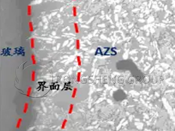
Currently, float glass melting furnace tank walls use large, single-piece bricks—usually dry-laid with vertical joints using a knife-handle pattern—generally made of AZS33 fused bricks. This type of wall has no horizontal joints, uses higher-grade materials, erodes more slowly, causes less contamination of the molten glass, and has a longer service life, making it widely used. The wall thickness has been reduced from 300mm to 250mm.
As expectations for furnace lifespan continue to rise, exploration of tank wall structures continues. After 2000, knife-handle-shaped tank wall bricks were applied and widely adopted in float glass melting furnaces. The material used is AZS33 and AZS36 electrofused bricks, and some companies also use AZS41 electrofused bricks. However, AZS41 electrofused bricks have poor thermal stability and are prone to cracking during kiln firing. Therefore, the thinner the pool wall, the better the cooling effect of the cooling air. Using knife-handle-shaped bricks allows for two-stage brick binding and slows down the erosion rate, thus greatly extending the lifespan of the pool wall (up to 10 years or more).