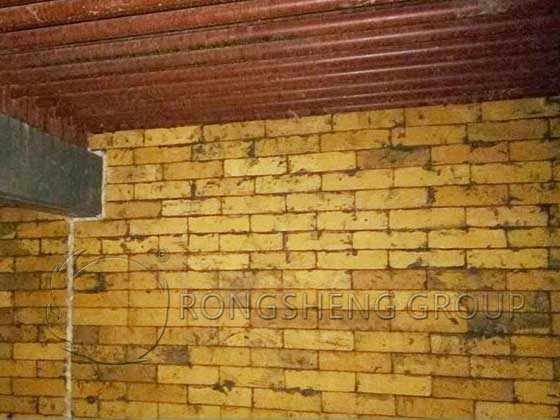
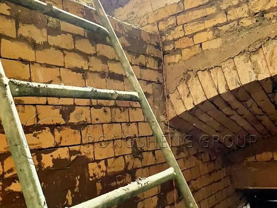
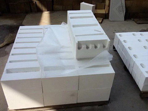
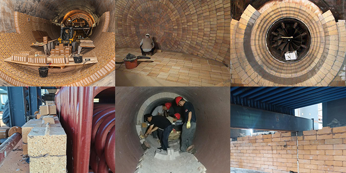
A meticulously designed furnace requires precision masonry. The quality of the masonry significantly impacts the furnace’s service life, fuel consumption, processes such as glass melting and fiber drawing, and metal smelting operations. To meet fundamental requirements regarding refractory masonry dimensions and thermal expansion, components such as tank wall blocks and bottom paving blocks must undergo cutting and grinding. Furthermore, the proper provision of expansion joints between refractory bricks is a critical step. Using a glass furnace as an example, this article outlines the masonry sequence and methods for refractory materials—approaches that can be adapted to other types of furnaces.
① Construction of the furnace bottom (including the forehearth bottom). After laying the insulation bricks and large kaolin bricks, level the surface, extending the layout 30–50 mm beyond the inner and outer faces of the planned sidewalls. For multi-layer bottom structures, construction must be controlled to stay within the negative elevation tolerance; the permissible deviation for the total bottom thickness is generally 3 mm. A layer of chromite ramming material is applied over the large kaolin bricks as a sealing layer to prevent molten glass from seeping into the underlying clay brick layer, which has lower corrosion resistance.
② Establishing centerlines. Once the furnace bottom steel structure has passed inspection, mark the centerlines for the batch charger, front and rear rows of bubblers, and the fiber-drawing bushings in the forming forehearth, based on the furnace construction reference lines and the furnace centerline.
③ Hoisting and erecting columns. Use temporary measures to stabilize the columns, then install the angle irons (skewback supports) according to design specifications; the columns and angle irons must fit tightly together, and the elevation must be precisely set.
④ Construction of sidewalls (including forehearth sidewalls). The base bricks for the sidewalls must be perfectly level; if necessary, the bottom bricks in this area must be dressed until they meet requirements. When laying multi-layer sidewall bricks, proceed from the inside out while ensuring the correct internal furnace dimensions; it is strictly prohibited to have cut or hewn brick surfaces facing the furnace interior. Corner joints must be staggered (interlocked), and verticality must be strictly maintained.
⑤ Construction of breastwalls, front walls, rear walls, and forehearth combustion spaces. Breastwall construction should commence only after the support brackets, plates, and frameworks have been inspected and approved. Measures must be taken to prevent hanging bricks and breastwall bricks from tipping into the furnace during installation.
⑥ Construction of the main arch. Construct the arch centering (formwork) and perform load-bearing settlement tests and dimensional checks. Lay the main arch bricks simultaneously from both sides toward the center; the work must be continuous and completed as quickly as possible. Installation of the main arch insulation layer takes place after the furnace heat-up (drying) process is complete.
⑦ Construction of flues and chimneys. Masonry work must commence only after all debris has been removed from the furnace interior and the area has been thoroughly vacuumed. The construction of the melting furnace flues and the stack must be coordinated with the installation of the metal heat exchanger; specifically, the stack serving the forehearth channel must not be built until the masonry of the channel itself is complete.
Kiln masonry methods are categorized into two types: wet laying and dry laying.
Wet laying areas: Side walls and crown arches in the flame space of the melting section; flues, chimneys, and insulation brick layers. The mortar used for wet laying must be a refractory mortar formulated specifically for the type of refractory brick being used.
Dry laying areas: Tank bottoms and side walls in the melting section and working channels; hanging bricks in the flame space; crown arch bricks in the melting section and flues; fused-cast brick masonry; and roof cover bricks for the working channels.
Kiln inspection and maintenance
The overall inspection and maintenance of the kiln cannot be overlooked; these factors directly impact production capacity, the ability to achieve design output, and whether the finished products meet quality requirements.
First, check whether the internal kiln passages are clear, if there are any obstructions affecting the under-car cooling system, and if the under-car cooling fans are operating correctly.
Second, examine the actual condition of the internal rails to check for deformation that might impede the movement of kiln cars.
Third, inspect the sand seal troughs inside the kiln for deformation that could compromise the seal.
Fourth, check the sealing between adjacent kiln cars.
Fifth, verify that the kiln car propulsion system is functioning normally and can transport cars to the required positions.
Sixth, check that the cooling air system is operating properly.
Seventh, inspect ventilation ducts for blockages and ensure smooth airflow throughout the entire kiln.
Eighth, verify that the waste heat recovery and exhaust systems are functioning correctly and not interfering with normal kiln operations.
Ninth, inspect the kiln structure for cracks that could cause air leakage or require repair, and assess whether the insulation integrity has been compromised—potentially leading to increased heat loss during operation.
Kiln Maintenance
Kiln maintenance requires careful attention to managing accumulated water and drainage around the kiln. Excessive groundwater or surface water can soften the foundation and reduce its load-bearing capacity, potentially causing structural shifts and cracks in the kiln body.
Maintaining good ventilation inside the kiln is essential. During winter or periods of inactivity, all materials should be fully fired and removed to leave the kiln chamber empty. Proper ventilation prevents the kiln structure from absorbing excessive moisture from the air, thereby avoiding damage when the kiln is fired up again.
Metal piping on the kiln is susceptible to oxidation and corrosion during high-temperature, high-humidity operations. Routine maintenance should include thorough inspections and the application of anti-corrosion treatments to prevent damage that could disrupt normal production.
During operation, the interior of the kiln is exposed to high-temperature erosion, which can cause the inner walls to spall or flake. Applying a protective coating—designed to withstand direct contact with the flames—helps extend the kiln’s service life.
Masonry Procedures for Common Industrial Furnace Walls
Masonry Procedure for Straight Furnace Walls
(1) Straight walls are constructed using the method of erecting guide poles and stretching horizontal lines. When both sides of the wall serve as working faces, horizontal lines must be stretched on both sides simultaneously during construction; the resulting masonry must be both level and plumb.
(2) Corners are the weakest points of a straight wall and require special attention during construction. Throughout the masonry process, the corner serves as the base for the wall structure and the reference point for laying each subsequent course of bricks; factors such as verticality, joint thickness, levelness, and the arrangement of longitudinal and transverse joints are all determined based on the corner. Consequently, the quality of the corner bricks directly impacts the quality of the entire wall masonry. Only intact bricks—free from chipped edges or corners and deformation, and of uniform thickness—should be used for the corners. Staggered joint masonry is typically employed, utilizing three-quarter bricks (171 mm in length) and half-bricks (114 mm in length).
(3) Layout and marking for the furnace body: Before masonry begins, the furnace foundation must be leveled using refractory castable. Subsequently, layout lines are marked according to the construction drawings. First, the longitudinal and transverse centerlines or transverse reference lines (e.g., based on the boiler’s 1-meter elevation mark) are established; then, the wall outlines for various components (including refractory bricks, lightweight insulation bricks, etc.) are marked. During layout, it is crucial to proceed from the inside outward, using the centerlines as the reference; marking from the outside inward is strictly prohibited to ensure the correct dimensions of the furnace chamber.
(4) If the straight wall is composed of two or more types of bricks (such as in boiler furnace walls), measures must be taken to prevent separation and ensure stability. For every 6 to 8 courses of refractory bricks, an interlocking masonry method—tying the inner and outer walls (refractory and lightweight insulation bricks) together—must be employed to maintain the structural integrity and stability of the furnace wall.
(5) During construction, attention must be paid to providing expansion joints between the furnace wall and the furnace bottom, the furnace roof, and any pipes passing through the straight sections of the wall.
(6) During construction, inspection tools should be used frequently to check the verticality and horizontality of the furnace wall, as well as the thickness of the brick joints.
Laying Procedure for Refractory Bricks in Circular Walls
(1) Circular furnace walls constitute the lining masonry of thermal kiln equipment and should be constructed based on the centerline. Once the vertical and radial deviations of the furnace centerline meet the internal dimensional requirements, the furnace shell may serve as the guide surface for masonry construction.
(2) Curved walls should be constructed using templates for layout and alignment; template lines should be frequently used for verification during the laying process.
(3) For furnace walls incorporating anchor bricks or hanging bricks, the load-bearing face of the brick slot must be positioned close to the hanger, while clearance must be maintained between the other sides of the slot and the hanger to prevent binding.
(4) Circular furnace walls must not be constructed with three consecutive layers of aligned vertical joints or three consecutive rings of aligned through-joints; aligned joints in vertically adjacent layers or horizontally adjacent rings must not coincide at the same location.
(5) The surface of the furnace wall at the skewback bricks must be leveled to the design elevation, ensuring a smooth finish; the distance from the skewback bricks to the centerline must comply with design specifications.