Traditional furnace linings are primarily constructed using carbon bricks (three layers at the bottom and a ring of bricks around the furnace walls). While carbon brick processing technology has improved, increasing brick width from 400mm to 800mm, joints between bricks are still unavoidable. Although grooves have been added to the sides of the carbon bricks to enhance the connection strength using mortise and tenon joints, this approach doesn’t always yield the desired results. Semi graphite carbon blocks for ferro silicon sub merged arc furnace lining. Similar experiments conducted on ferrosilicon furnaces showed that the grooves on the sides of the carbon bricks at the furnace bottom had little effect. Improper installation, such as poor joint sealant flow, could even have the opposite effect.
Basic Parameters
- Furnace Diameter: φ7600mm.
- Furnace Shell Inner Diameter: φ9400mm.
- Furnace Depth: 3300mm.
- Furnace Shell Height: 5550mm.
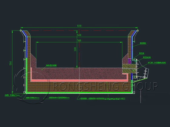
Overall Description
- The furnace bottom and wall lining are made of asbestos board and HC-type high-conductivity paste.
- The furnace bottom consists of 5 layers of secondary high-alumina bricks, 6 layers of primary high-alumina bricks, CCS-type cold-rammed paste, and K-type cold-rammed paste.
- The taphole is composed of semi-graphite carbon-silicon carbide bricks (irregularly shaped monolithic bricks), corundum castable, and CCS-type cold-rammed paste.
- The outer side of the furnace wall is made of 75# high-alumina bricks, HC-type high-thermal-conductivity paste, and K-type cold-rammed paste.
- The top area of the furnace wall is made of high-alumina bricks.
- The connection joints between the semi-graphite silicon carbide bricks and the K-type cold-rammed paste and the high-alumina bricks of the furnace wall.
Investigation and Research on Damage to the Ferrosilicon Submerged Arc Furnace Body
As the furnace body operates for an extended period, the refractory materials inside the ferrosilicon submerged arc furnace become thinner due to erosion and oxidation caused by high-temperature molten iron, severely affecting the safe operation of the furnace.
- (1) Through investigation and analysis of damage during the dismantling of the ferrosilicon submerged arc furnace body, the areas with the deepest erosion of the bottom carbon bricks were the furnace core area and the tapping hole area, while other areas showed relatively less erosion.
- (2) Actual inspection of the furnace bottom damage revealed that the bottom carbon bricks were damaged and leaking iron, seriously affecting the safe operation of the furnace bottom. It can be inferred that during the construction of the bottom carbon bricks, some of the gaps were too wide, leading to iron leakage during furnace drying and smelting. Therefore, it is essential to ensure tight gaps in the bottom carbon bricks when constructing the furnace body refractory materials.
- (3) From the perspective of furnace wall damage, the most severely damaged area was the tapping hole area. Therefore, manual tapping of the tapping hole is strictly prohibited during subsequent production; a dedicated tapping hole opening machine must be used. Ensure the furnace borehole is properly sealed, with the depth controlled to a level comparable to the furnace wall thickness. Simultaneously, use anhydrous taphole clay instead of wet taphole clay to enhance the erosion resistance of the furnace borehole channels. Maintain the furnace borehole channels and internal structure to slow down the erosion rate of the refractory materials inside the furnace wall.
- (4) During the smelting process in the ferrosilicon submerged arc furnace, control the appropriate electrode working end length to form a stable silicon carbide layer 3 at the furnace bottom to protect the furnace bottom carbon bricks. While ensuring sufficient electrode length, prevent excessive electrode depth from eroding the furnace bottom carbon bricks.
- (5) The erosion calculation of the refractory materials inside the furnace body is based on theoretical thermal conductivity under ideal conditions and contains certain errors. It can only be used as a reference for erosion calculation during the smelting process.